MIL-DTL-85069D
NOTES:
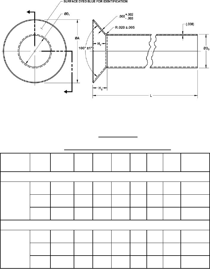
1. Dimensions are in inches and shall apply prior to surface finish. Refer to table V.
2. Grommets may be procured in standard required lengths or may be adjusted to required length as
needed.
FIGURE 3. Grommet fastener.
TABLE V. Grommet fastener - part numbers and dimensions.
ØDI
ØDO
L3
MS dash Fastener
ØA
Drill
MS part
2
max.
max.
HF
HS
diameter 4
number 1
number
size
±0.005
±0.010
min.
min.
Reduced head, swaged, countersunk, panel fastener
08
1/4
0.393
0.2545
0.2706
0.061
0.066
1.00
0.273
0.2530
0.2696
10
5/16
0.472
0.3170
0.3331
0.068
0.073
1.00
0.334
M85069/10
0.3155
0.3321
12
3/8
0.558
0.3795
0.3956
0.078
0.083
1.00
0.398
0.3780
0.3946
Tension head, swaged, countersunk, panel fastener
08
1/4
0.505
0.2545
0.2706
0.108
0.113
1.00
0.273
0.2530
0.2696
10
5/16
0.631
0.3170
0.3331
0.135
0.140
1.00
0.334
M85069/11
0.3155
0.3321
12
3/8
0.758
0.3795
0.3956
0.162
0.167
1.00
0.398
0.3780
0.3946
1
MS part numbers retained for legacy support purposes.
2
Reference dimensions are for design purposes only and are not an inspection or manufacturing requirement.
3
Uncut grommet length is 1.000 inch. Before installing, cut grommet length to equal panel thickness (see figure 4).
4
Special drill is required.
13
For Parts Inquires call Parts Hangar, Inc (727) 493-0744
© Copyright 2015 Integrated Publishing, Inc.
A Service Disabled Veteran Owned Small Business